Rudy Ramos, Mouser Electronics
Just about every electronic system has some form of power conversion. These days, efficiency is an often-used word whether it is to conserve battery power to extend operating life, or to reduce energy costs (and waste heat) in data centers.
Even in the most efficient systems, efficiency never reaches 100%, all systems convert some energy to waste heat. If thermal issues are not managed effectively then reliability becomes an issue, especially in heat-dissipating components such as power transistors or resistors. If these components get too hot then their lifetime is reduced and, in extreme cases, exceeding maximum ratings can result in immediate destruction.
At the heart of reliability is the Arrhenius Law, where temperature is a key predictor of lifetime. As a guide, the lifetime of a component can be doubled by reducing the operating temperature by 10°C. A further benefit of reducing operating temperature by managing heat better is allowing more power to be delivered, or for the system to be able to operate at higher ambient temperatures.
In the switching devices, any power that is not transferred from the input to the output is known as ‘losses’ and is dissipated as heat in the semiconductor junction. This can be calculated as follows:-
Tjmax = (PDmax x Rθja) + Ta
Where:-
Tjmax = maximum junction temperature
PDmax = maximum power dissipated
Rθja = thermal impedance from junction to ambient
Ta = ambient temperature
Designers aim to achieve a junction temperature that is optimal for the components selected, thereby ensuring no early failure and also ensuring that reliability is enhanced. To do this they rely on manufacturer’s data – the maximum power dissipation of a device can be found from the datasheet as can the thermal impedance from the junction to the ambient (outside of case), θja.
If, in a given application, it is not possible to achieve an acceptable junction temperature then designers will seek to modify θja until the junction temperature is at the required level. There are various ways of achieving this, including:-
- Selecting advanced semiconductor packages with technically advanced features such as clips that replace wirebonds, reducing internal resistance and increasing current carrying capability. Other useful innovations include large metallization on the upper or lower side of the die (or both sides!), which help with heat transfer. These metal pads are directly connected to a heat slug or exposed metal pad that can be attached to an external heatsink or soldered directly to a PCB to disperse heat.
- Modifying the board design to add thermal vias close to heat-generating components and adding a heat spreader such as a heavily metallized layer. Even increasing copper thickness can help with heat dissipation but in extreme cases an insulated metal substrate (IMS) may be considered.
- Traditional techniques such as heatsinks or fans will always improve heat dissipation and in more extreme applications, such as high-reliability military applications, heat pipes provide a robust solution.
As with almost every engineering decision, there is a trade-off between effectiveness of the solution, size, weight and the overall Bill of Materials (BOM) cost of the solution. If the solution is under-engineered then reliability will be impacted, possibly leading to premature failure while if the solution is over-engineered then the end product may be too large, heavy and expensive.
Project timescales may preclude building several prototypes to experiment with different thermal solutions. However, if the initially selected solution is found to be inadequate then a mid-project redesign may be impractical or, at best, highly expensive.
To gain more confidence in the design at an early stage, thermal simulation software packages can allow engineers to plan and simulate system thermal performance before committing to any hardware or expense, increasing the chance of success with a first prototype.
TI’s WebTHERM™ is an example of a package that is available online for no charge. This performs thermal analysis for any power supply design developed using the online WEBENCH® environment. Created as a WEBENCH project, the power supply is using the selected controller or DC/DC converter IC. Basic requirements such as input and output voltage ranges are then added to complete the model.
Once this step is completed, WEBENCH compiles the BOM and derives values for power dissipation and θja. Engineers could use these values to calculate Tjmax manually, as ambient temperature is known / defined. However, WebTHERM shows simulated thermal performance graphically, and also includes detailed secondary effects such as co-heating of adjacent components that can be almost impossible to predict. WebTHERM delivers a color temperature plot that highlights any areas of the design that require further investigation or tweaking.
Running a simulation starts with the user entering settings including load current, high and low ambient temperature, and maximum permissible device case temperature. A thermal simulation takes just a few minutes to run, delivering data that can be analyzed graphically using the color temperature plot. If adjustments are required, the design can be altered within WEBENCH to address areas of concern and then a further simulation can be performed.
Multiple simulations can be performed and compared side-by-side to identify how different thermal management techniques impact the system. While this could be done manually (in theory) it would take significant time and expense to produce multiple prototypes, while the simulated temperature plot can take the engineer straight to the areas of primary concern.
Heatsinks
Heatsinks are incredibly simple to understand; they have no moving parts and are unlikely to fail unless damaged. They also cost nothing to operate. Most often they are either aluminum or copper and run the gamut from simple stamped shapes that affix to a discrete semiconductor through to complex shapes that are extruded and / or milled to maximize the effect of any available airflow as well as to fit the available space in the design.
Even if there is no forced airflow from a fan, it can occur as a result of naturally-occuring convection due to warmed air rising. With any airflow mechanical layout must ensure and unimpeded (as much as possible) path from air inlet to outlet and it is also important that the inlet is low and the outlet high so that the warm air can rise naturally and avoid pockets of stagnant warm air.
Although very useful, if large amounts of heat are involved then heatsinks can become heavy, large and expensive. Placing them (and their associated components) in the best airflow may compromise board layout and circuit performance. During use, dust may gather on the surface or in the fins, degrading performance over time. They also add time, and often an extra process step, to the assembly process – especially when screws, clips or thermal interface material (TIM) are required.
A huge selection of heatsinks can be obtained from suppliers such as Aavid Thermalloy or Wakefield-Vette, including items that are tailored to fit standard size components, such as processors or FPGAs.
Another way of choosing a heatsink is by selecting based on its effect on reducing θja, the overall thermal impedance from the semiconductor junction to the ambient air surrounding the heatsink.
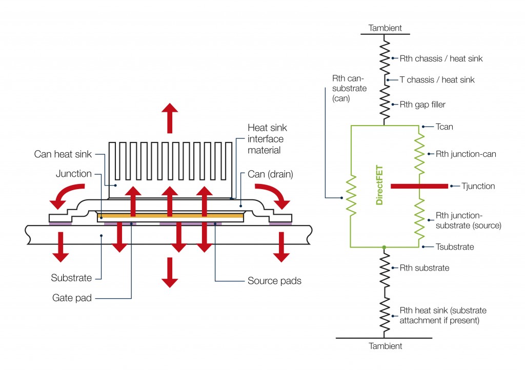
Figure 1 depicts a power transistor in a thermally enhanced package that delivers efficient dual-sided cooling using a top-mounted heatsink and a heat spreader in the PCB. The system is shown modeled as a network of thermal impedances, Rth, between the active junction and the ambient environment above and below the board. The thermal impedance of the heatsink, Rth heatsink, expresses how efficiently heat can be transferred from the base of the heatsink to the ambient environment.
Figure 1: Adding a heatsink to boost top-side cooling of thermally enhanced power package.

Heat pipes give designers further options
Depending on the design, there may be challenges such as size constraints or board layout requirements – or even impediments to a smooth airflow. Any of these could restrict, or ultimately prevent, the attachment of a heatsink to a heat-producing device.
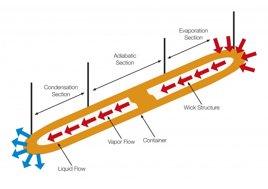
In these situations, a heat pipe (Figure 2) is a useful alternative. Heat pipes enable heat to be rapidly moved from a heat source to another area where a heatsink or spreader plate can be placed, taking advantage of greater airflow. The part shown, the Wakefield-Vette model 120231, is capable of handling thermal loads up to 25W yet is just 6mm × 100mm.
Heat pipes are not heatsinks in themselves. They are, in fact, sealed tubes that transfer heat from their hot end to their cool end through phase-change principles. Heat is absorbed at the hot end and this vaporizes the working fluid inside the tube. The vapor travels towards the cool end and condenses back into liquid releasing its heat in the process. The liquid then travels back to the hot end of the pipe to repeat the sequence.
No power is required to sustain this phase-change mechanism, there are no moving parts to fail and designers have complete freedom to position the heat pipe as required as no airflow is required either.
Figure 2: Heat pipes are available in various shapes and sizes, or can be customized, to transfer heat to a convenient place to be dissipated by a heatsink fan.

Fans: Active cooling
If passive methods such as heatsinks or heat pipes will not yield the desired results then forced-air cooling by a high-quality fan from a manufacturer such as Delta Electronics is an option. Fans allow cooling to be optimized by selecting a fan of a suitable size and then adjusting speed to manage the airflow, rated in cubic feet per minute (CFM).
Summary
Adequate thermal management is key to ensuring both high performance and longevity / reliability in power-related applications. While designers can draw on many techniques, they have to take care to not over-engineer, which can result in large, heavy and expensive designs that may not be successful. Adding too much complexity will also increase manufacturing time and cost.
Decent thermal simulation tools can be found online for no cost and these allow simulations to be carried out before any money is spent on prototype hardware. They are also quicker than building and debugging multiple physical prototypes.
In challenging applications engineers can draw on custom-machined heatsinks or heat pipes for passive solutions or move to a fan-based active cooling solution to meet the needs of the application.
Download Techmezine Android app on google play store: Download Now


