
Ever thought of controlling your RC car by your smartphone? Cool, huh? Well, that’s really not a hard task to make that type of cars or bots. In fact, if you have some experiences in the field of Robotics, you would know that it is quite common to make this type of bots as they are much simpler to control (also have much better and precise control than those DPDT controlled RC bots).
So, as we proceed to further details of making such bots, I should tell you that there are mainly two variants of these smartphone-controlled bots-
1)Accelerometer controlled (You can control your bot by tilting your smartphone)
2)Key controlled (Your smartphone’s app will contain 4 arrow keys for Up, Down, Left, Right. You can control your bot by pressing those keys)
We shall show you how to make bots of both variants. Now, let’s get to the work.
Requirements: – (Product Links are given below)
1) Bluetooth Module HC05
2) Arduino UNO or Genuino UNO
3) L298N(Recommended) or L293D motor driver module
4) 2 wheeled or 4 wheeled chassis
5) Motors – 2 or 4(according to your chassis. Number of motors=Number of wheels)
6) Batteries or any other power source to run motors.
Making of Chassis: –
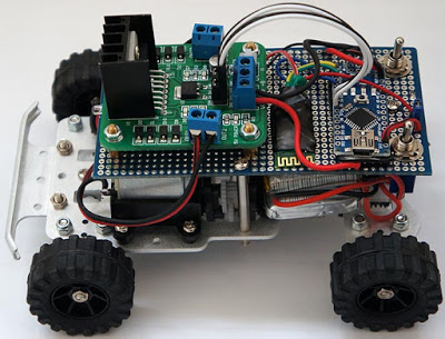
At first, make the robot body by assembling the robot chassis, motors, wheels and clamps (if needed).
Then if your chassis is of two wheels, add the caster and ball to your chassis and complete it.
If your chassis is of 4 wheels, connect two motors of left side with each other in same sense of rotation (i.e., they should rotate in the same clockwise or anti-clockwise direction if connected to same voltage source in parallel connection. You can easily check it and manipulate its connections if needed)
In this step, I think you should have got lots of free space on the top of your chassis. Add an Arduino, L298n motor driver (not L293d, if it is a 4-wheeler chassis. As, in practical case, we have seen L293d cannot take too much load and it does not have in-built facility of PWM and its Power efficiency is also low) and a small breadboard. Now add the Bluetooth Module HC-05 on the bot. Now, the chassis of our bot is ready.
Now, let’s get to the circuitry part.
Making Circuitry: –
Construct the circuit below.

1)Arduino GND-Battery (or other power source for driving motors)(12V) GND-L298(or L293) Motor Driver GND-Bluetooth Module GND
2)Arduino 5V-Motor Driver VCC (5V)-Enable 1-Enable 2-Bluetooth Module VCC(5V)
3)OUT 1, OUT 2-Right Motor
4)OUT 3, OUT 4-Left Motor
5)IN1- Arduino Pin 5
6)IN2- Arduino Pin 6
7)IN3- Arduino Pin 7
8)IN4- Arduino Pin 8
9)Arduino Pin 0 (RX)-TX Pin of Bluetooth Module
10)Arduino Pin 1 (TX)-RX Pin of Bluetooth Module
11)Power Source for driving motors(12 V) – Motor Source 12V Pin
Note: –
1)Some Bluetooth Modules are designed for working at 3.3 V. So, at first check this. If your Bluetooth Module is designed for working at 3.3 V, connect that VCC pin to Arduino 5V Pin through a 220-ohm resistor.
2)In circuit diagram, I have not shown the Power Sources (or Batteries). You have to add the power sources obviously. Also you have to provide 5V at EN 1 and EN 2 of Motor Driver.
Now its coding time.
Code Your Arduino: –
Upload the following codes to your Arduino. I have uploaded those Arduino codes along with a Readme file in a folder in Google Drive. You can easily download it.
Links: –
1)For Accelerometer controlled bot- http://gestyy.com/wJwyn3
2)For Key-controlled bot- http://gestyy.com/wJwy6K
When you are done with all these stuffs, Congo! Your smartphone-controlled bot is ready to run!
If you are facing any problem with the procedure or have found any bug or mistake, please let me know in the Comments section. You can also give me your valuable suggestions for improvement of this process.
COURTESY: TechieRka
Download Techmezine Android app on google play store: Download Now